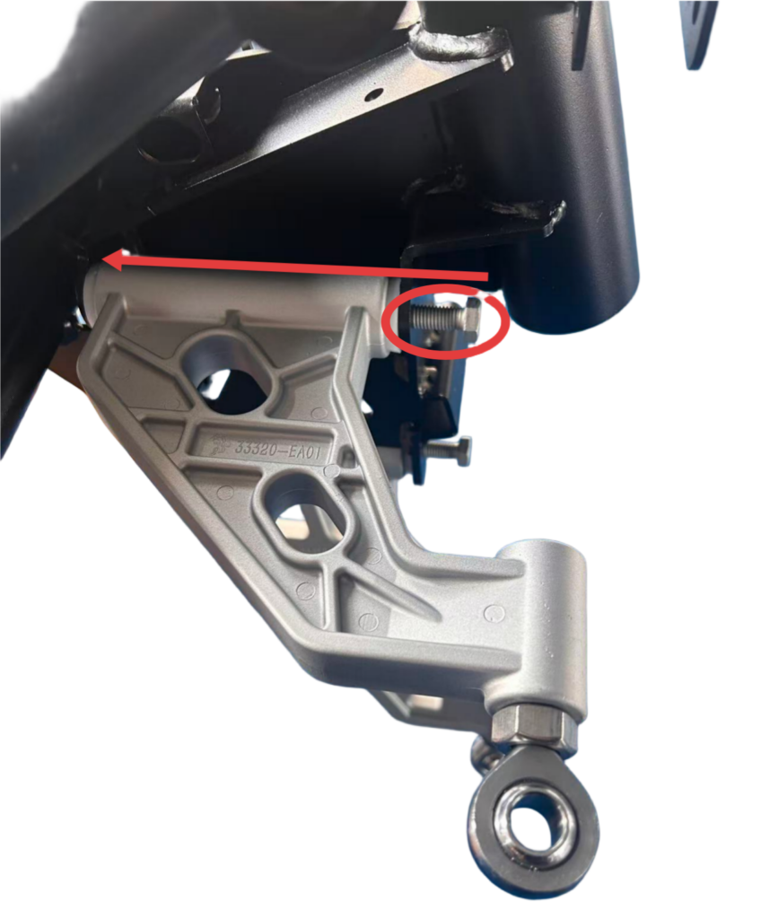
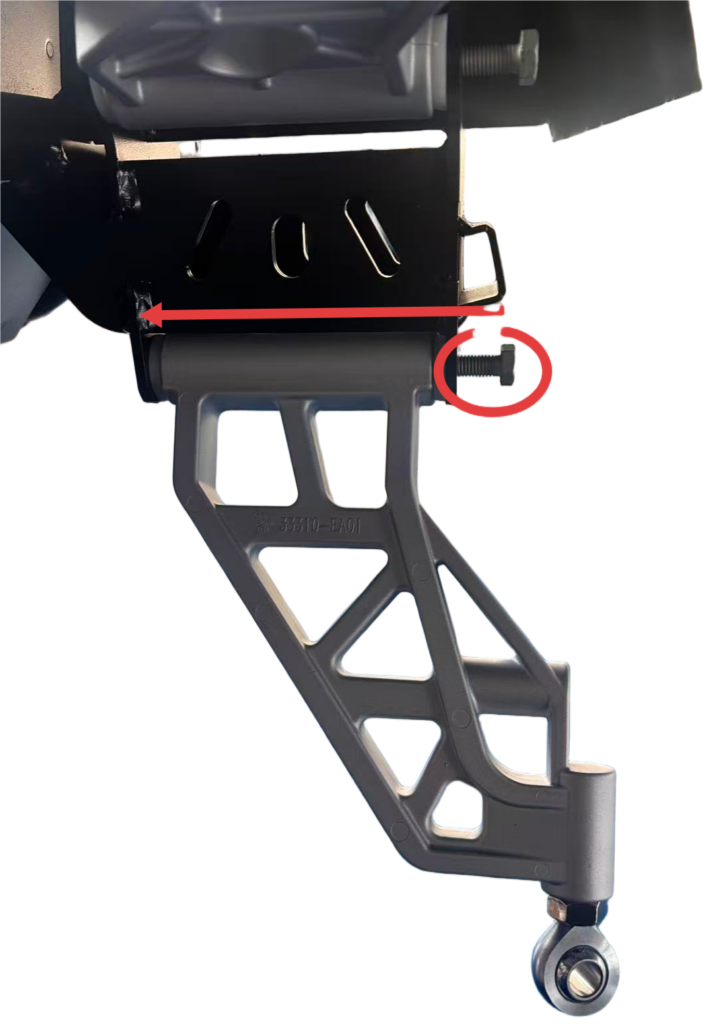
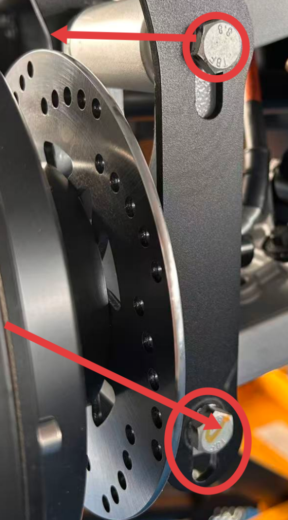
Make sure the upper and lower front A-arms are installed in the correct positions.
The front A-arms should face the direction shown in the diagram.
Do not fully tighten the bolts; the A-arms must remain able to move freely.
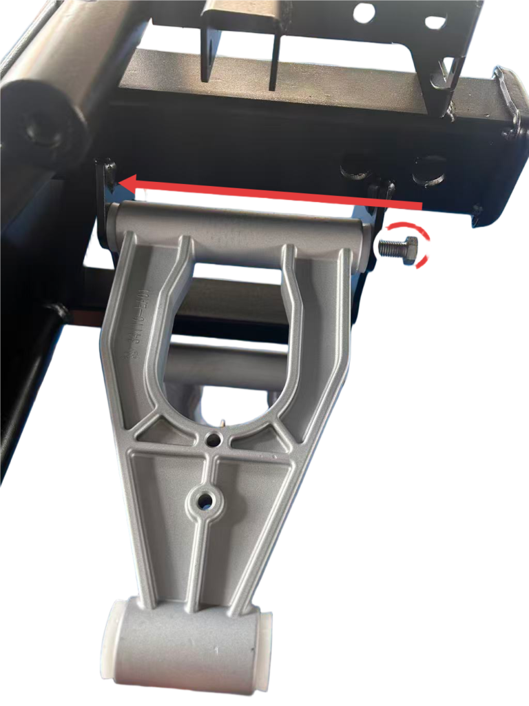
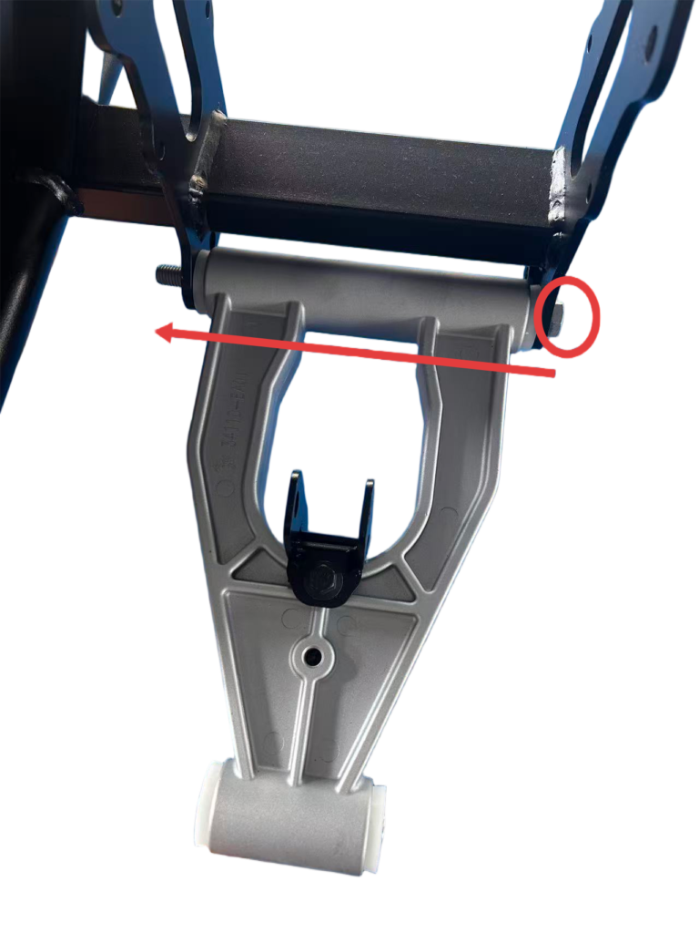
Step 2 Rear A-arm and frame assembly
Do not fully tighten the bolts.
The A-arm must be able to move freely.
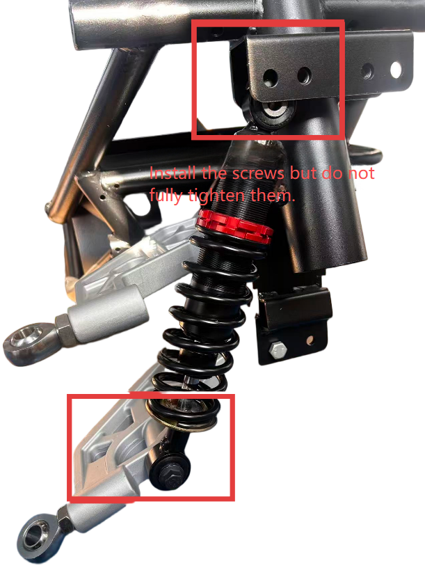
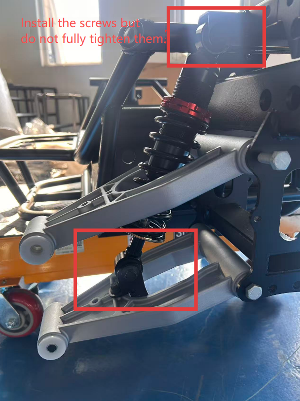
Step 3 Shock absorber and A-arm assembly
Note: Do not fully tighten the upper screws at this stage, to allow easier installation of the motor later.
Step 4 Front motor and A-arm assembly
The motor has left and right sides—please make sure to distinguish them correctly.
Do not fully tighten the upper shock absorber bolts until the motor has been installed.
Step 5
Rear motor and swingarm assembly
The motor has left and right sides—make sure to identify them correctly. Tighten the upper shock absorber bolts only after the motor has been installed.
Step 6
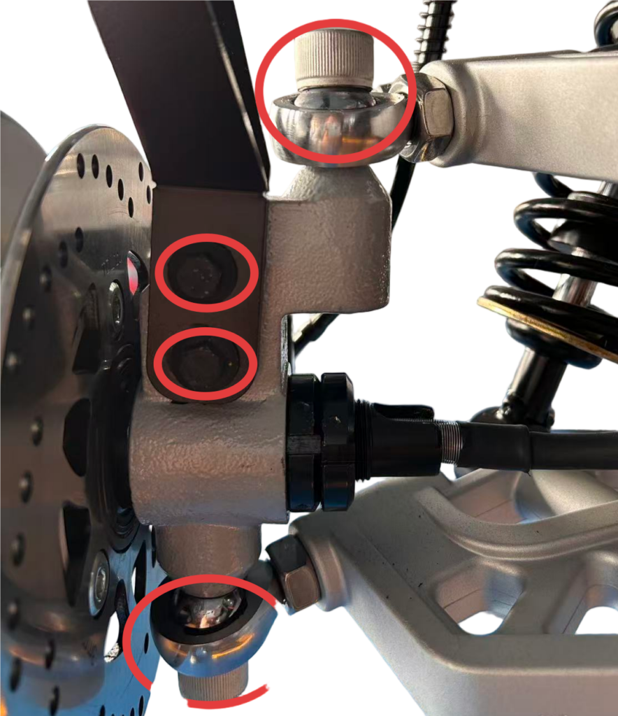
Tie rod assembly and steering knuckle assembly
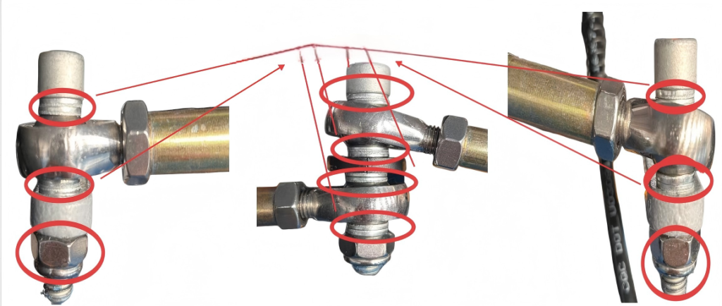
Install one retaining ring on each side of the bearing. When tightening, first use an electric wrench, then fully tighten with a hand wrench.
Step 7
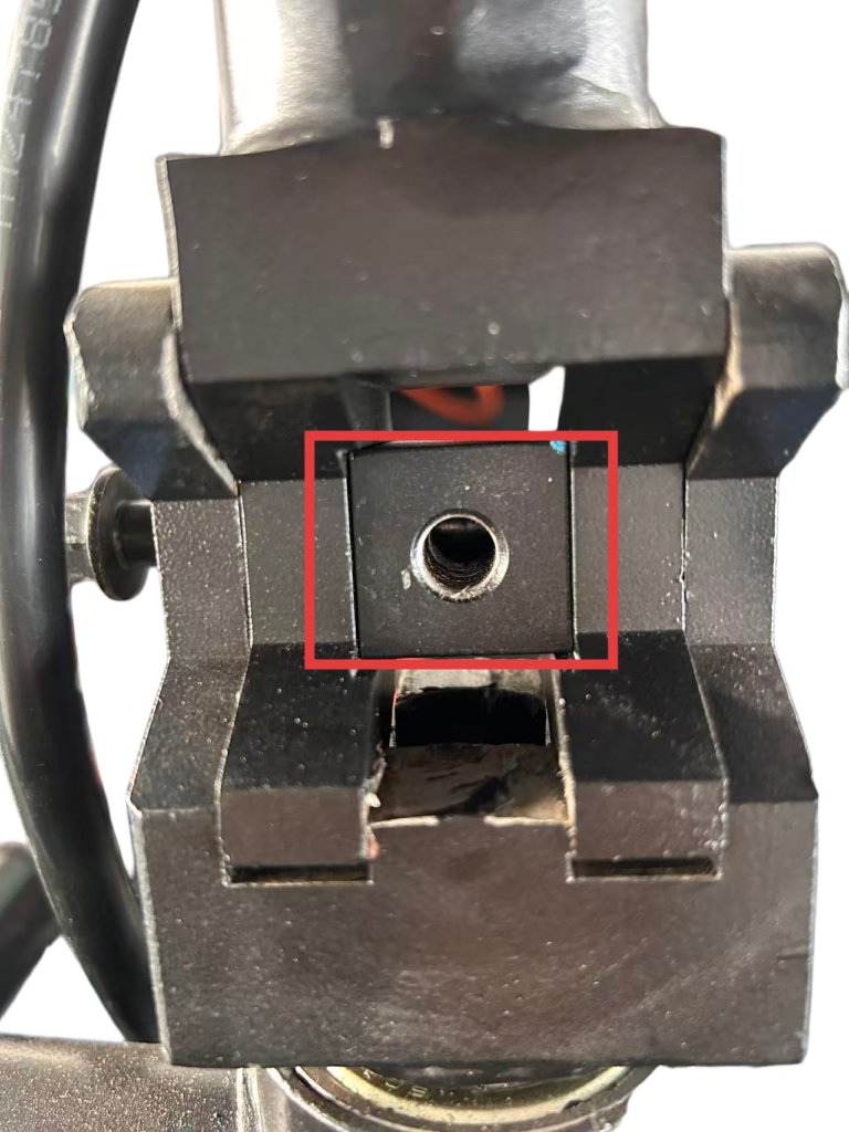
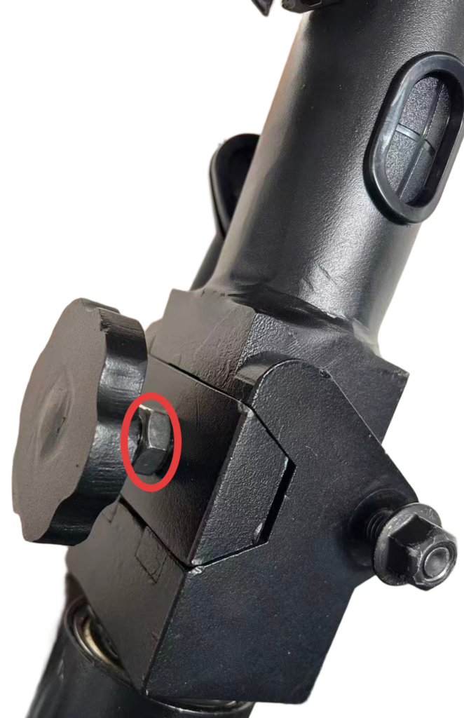
Upper steering assembly installation
Step 8
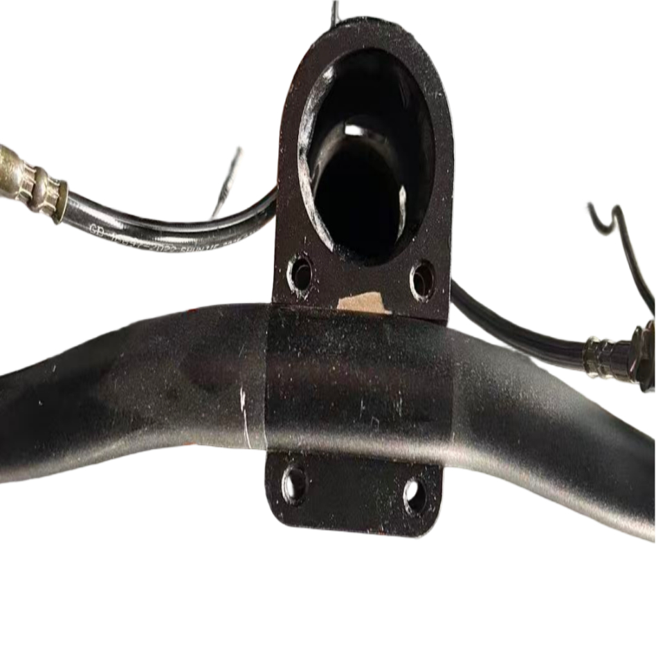
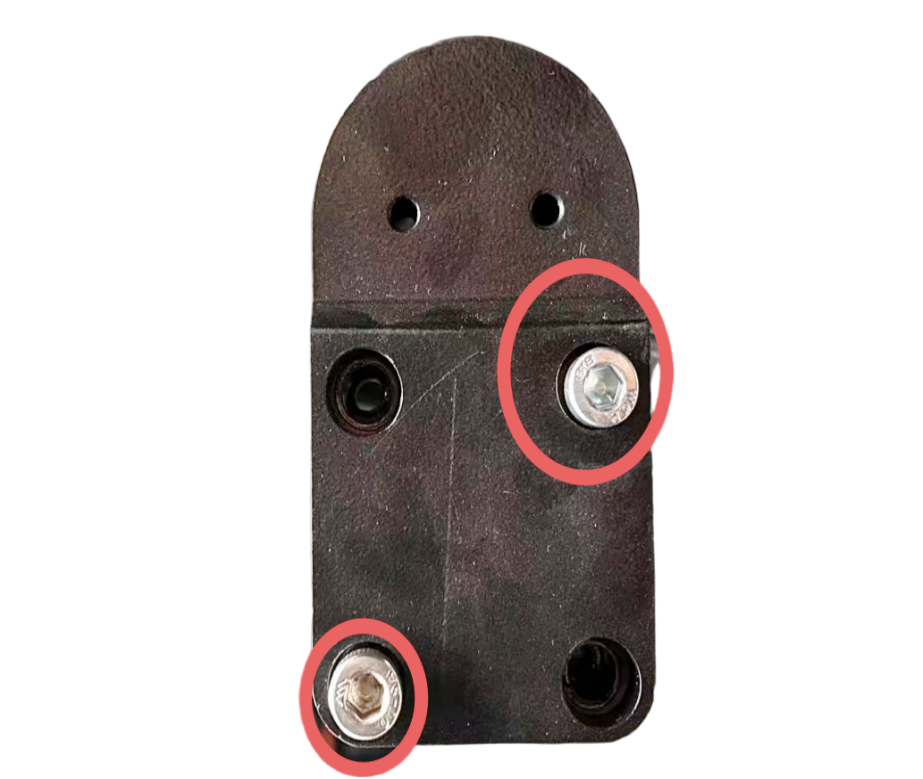
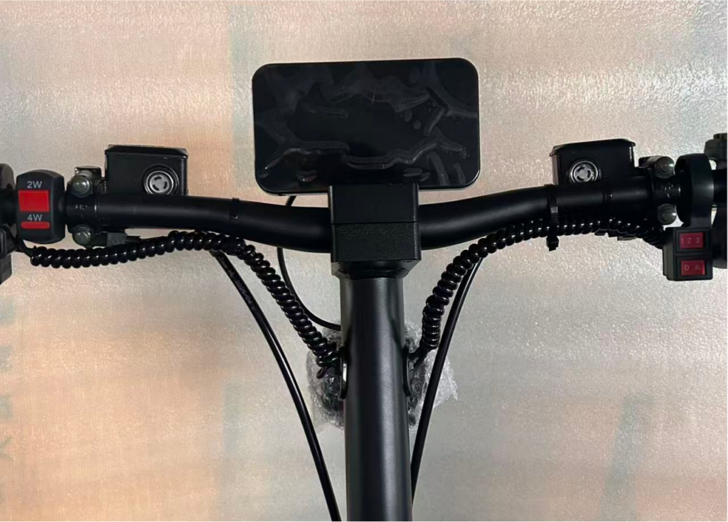
Handlebar assembly
After tightening the screws with an electric wrench, re-tighten them using an Allen key for final adjustment.
Step 9
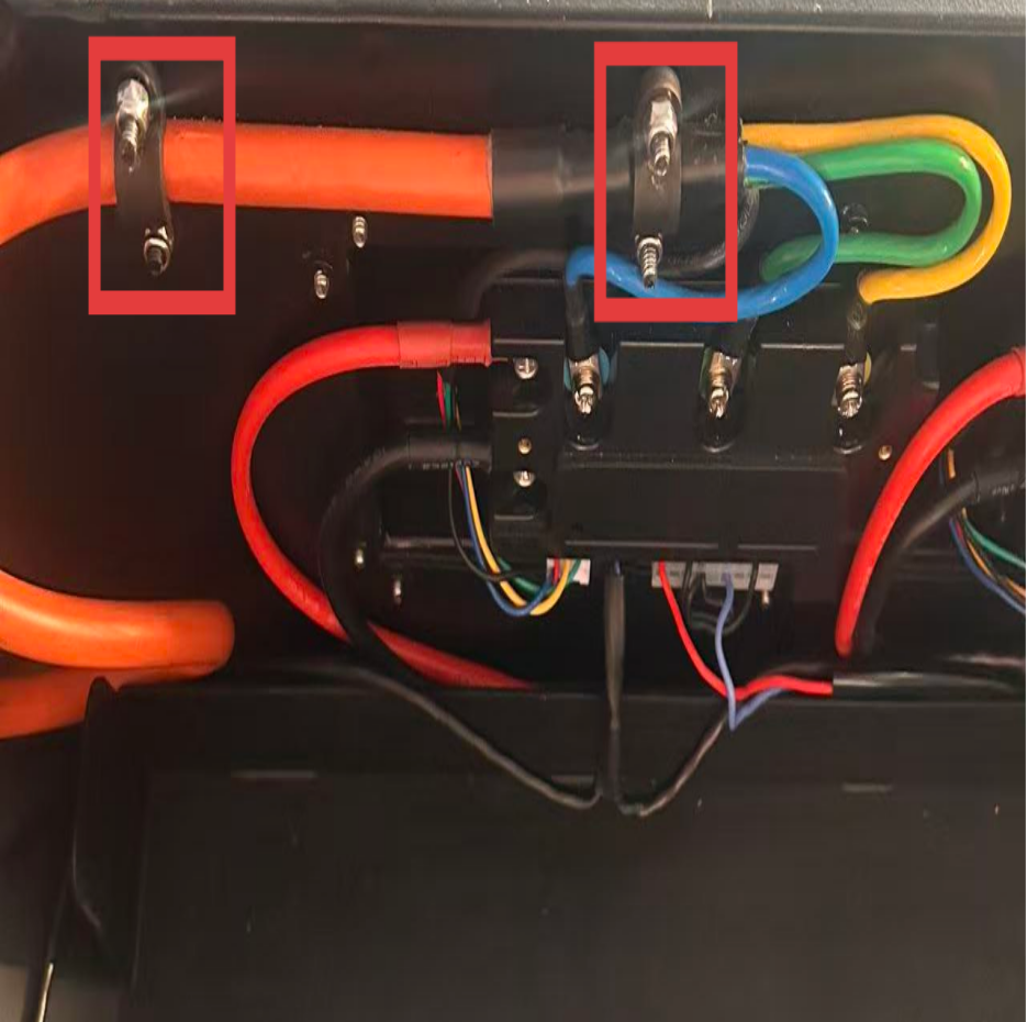
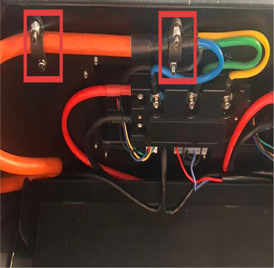
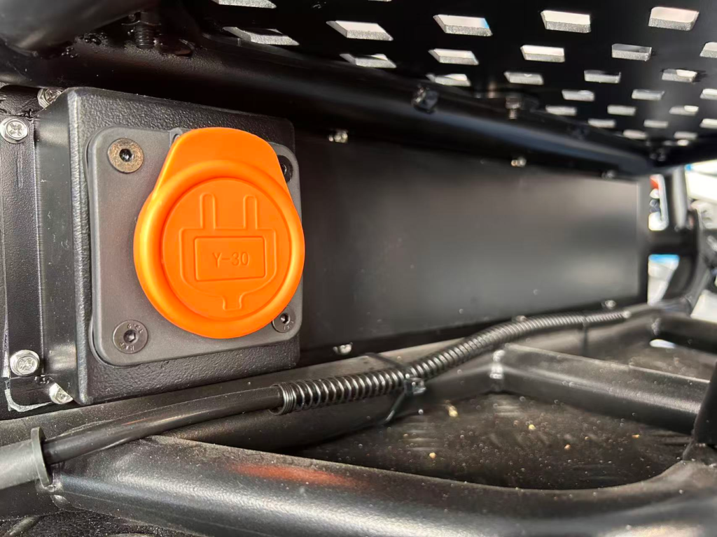
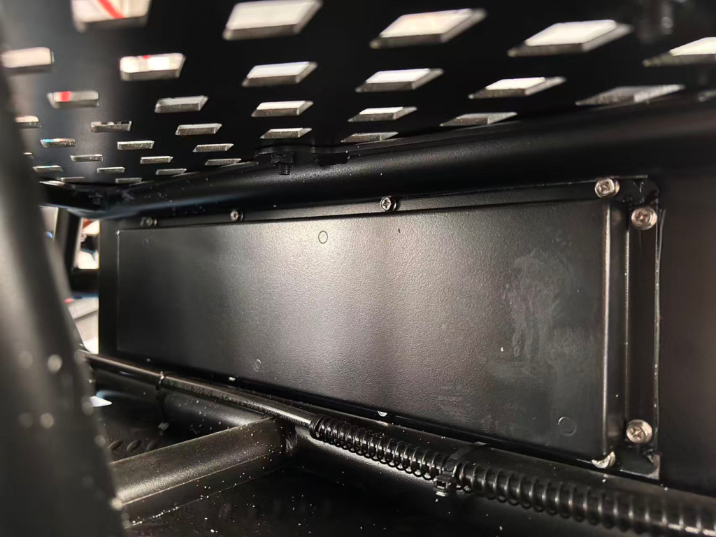
Controller box and frame assembly
Be careful not to strip the screws when using an electric wrench.
Step 10
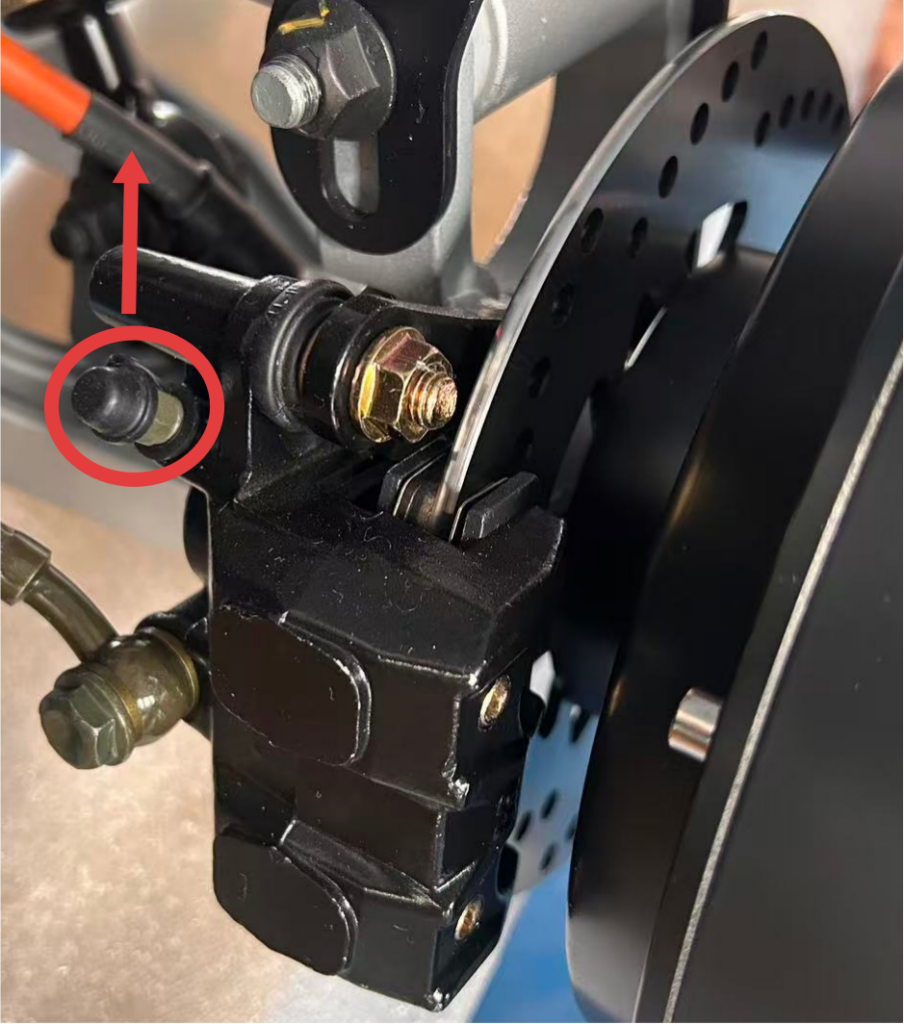
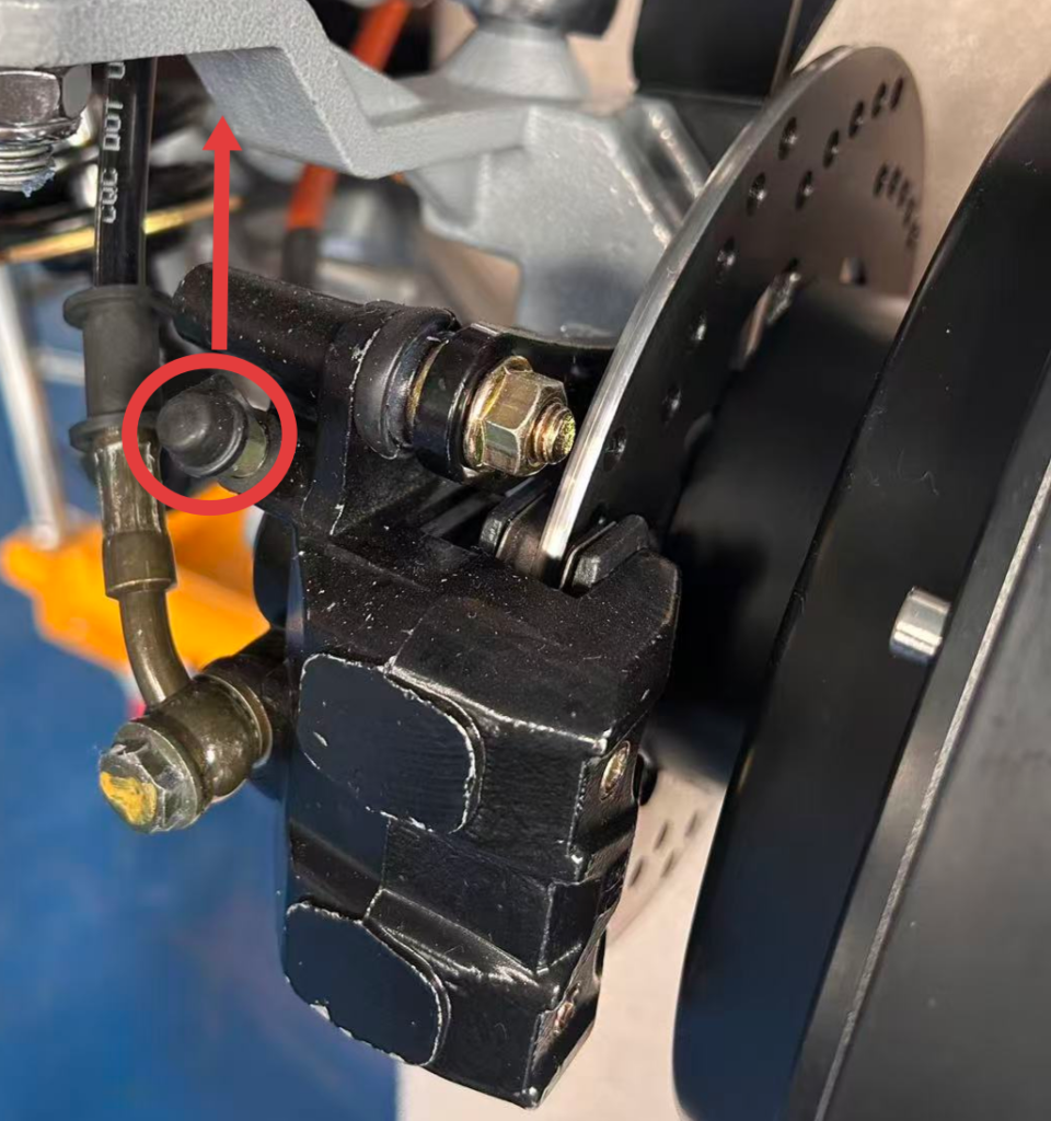
Brake oil pipe installation
Step 11
Brake caliper (lower pump) installation
When installing the lower pump, each bolt must be fitted with a spring washer.
Step 12
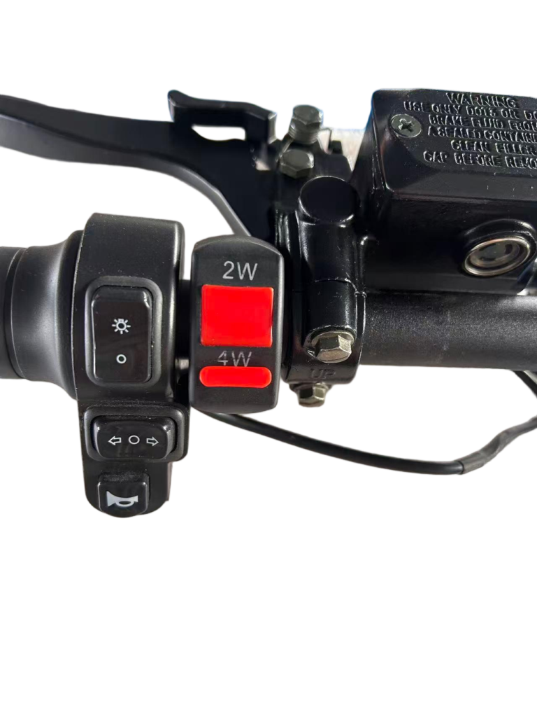
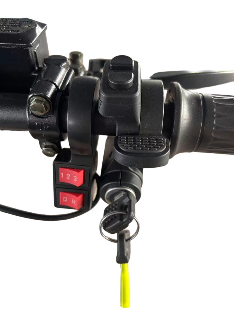
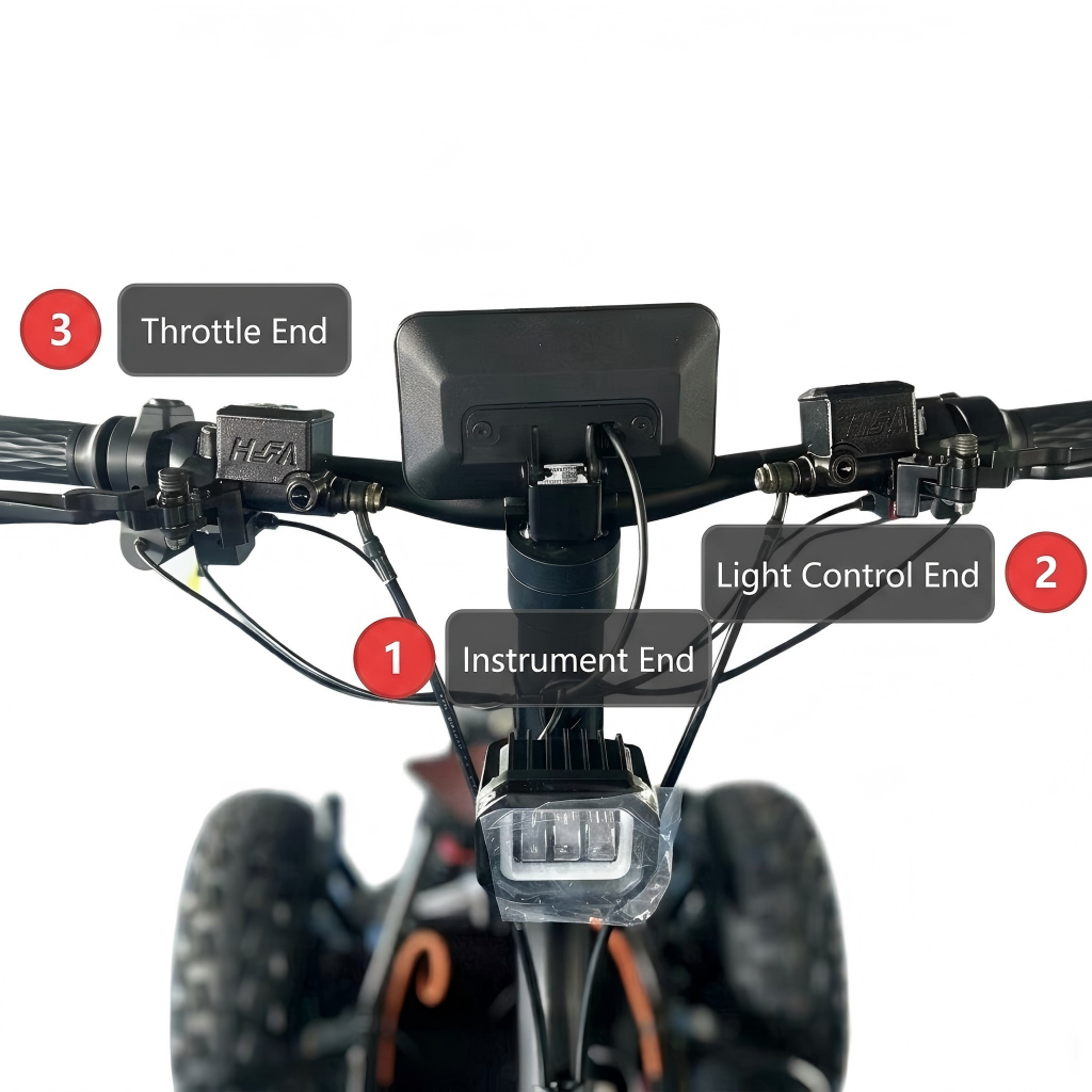
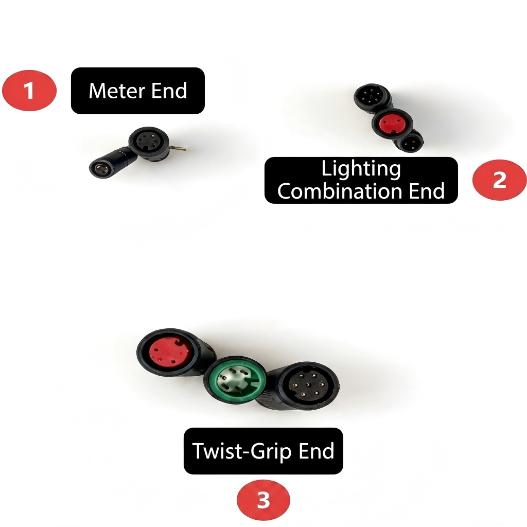
Handlebar switch assembly
There should be approximately a 1 mm gap between the thumb throttle and the handle grip.
Step 13
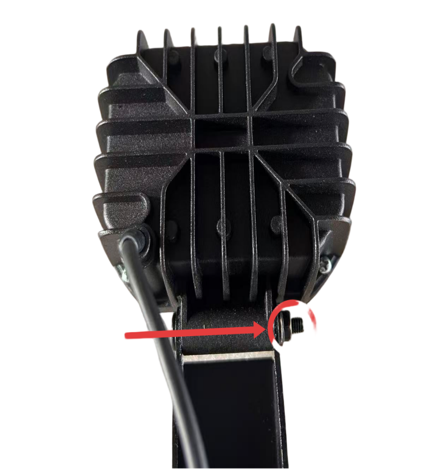
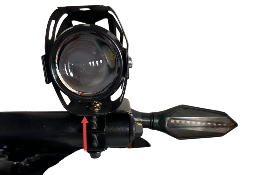
Headlight and turn signal assembly
Wrapping tape around the mounting points of the LED light is to protect the frame’s paint surface.
Step 14
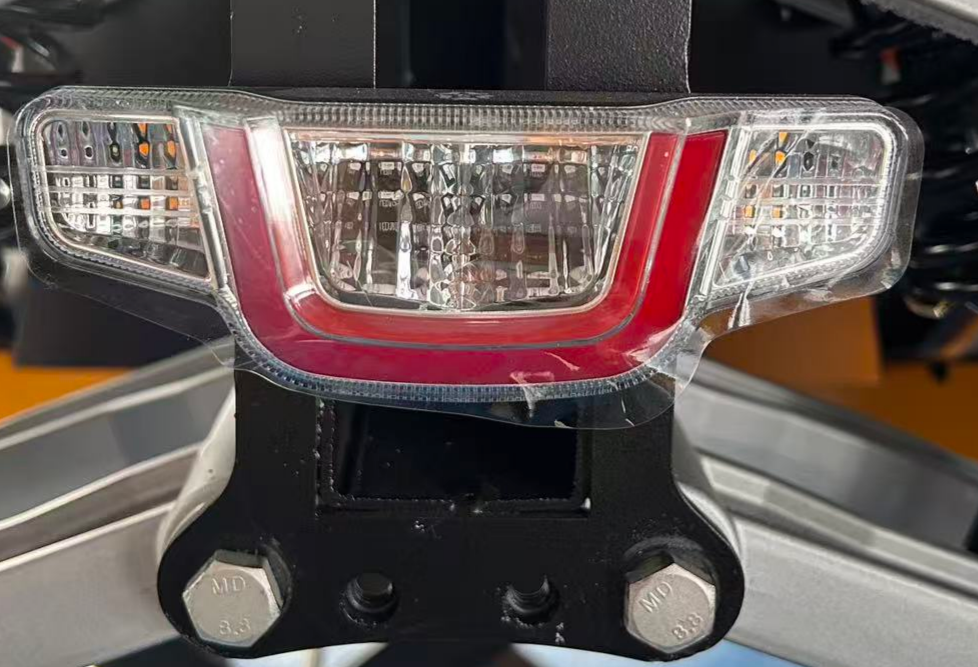
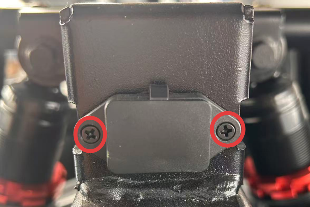
Rear taillight and 12V power assembly
When tightening the taillight nuts, tighten them just firmly—excessive force may cause the taillight screws to strip or pull out.
Step 15
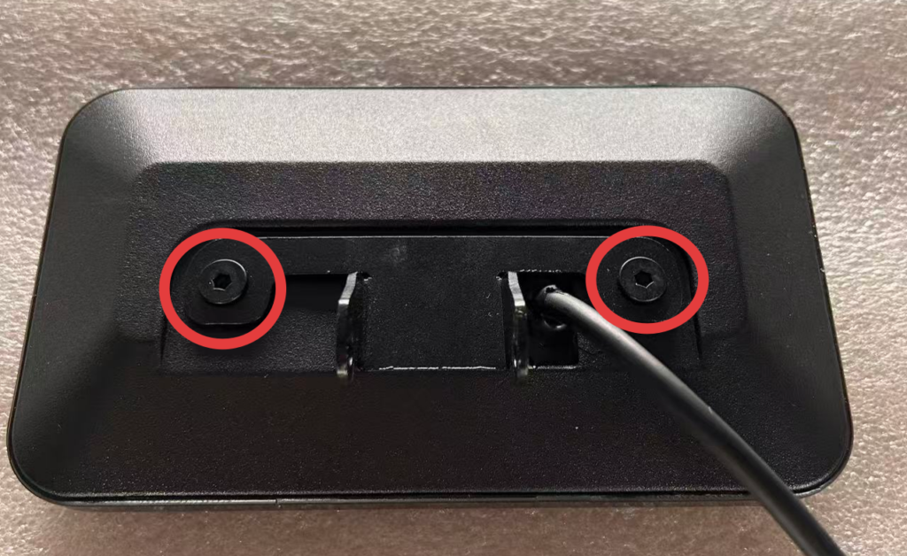
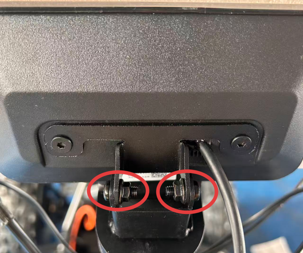
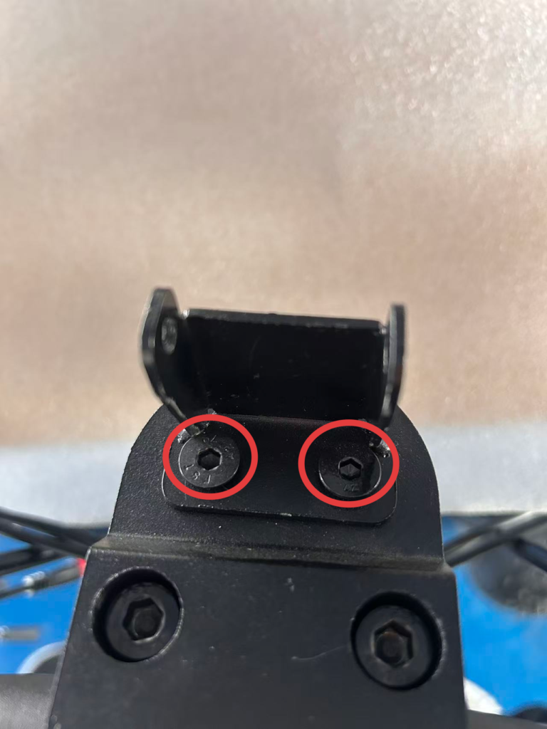
Instrument cluster assembly
Step 16
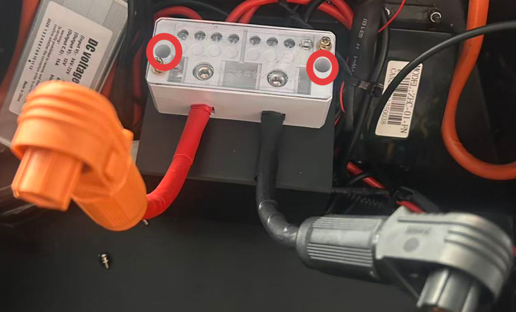
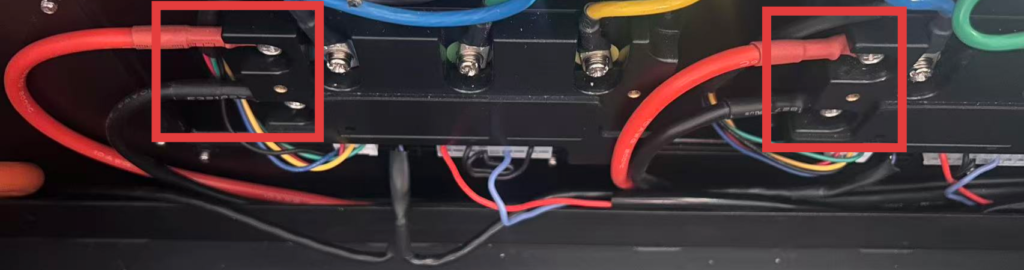
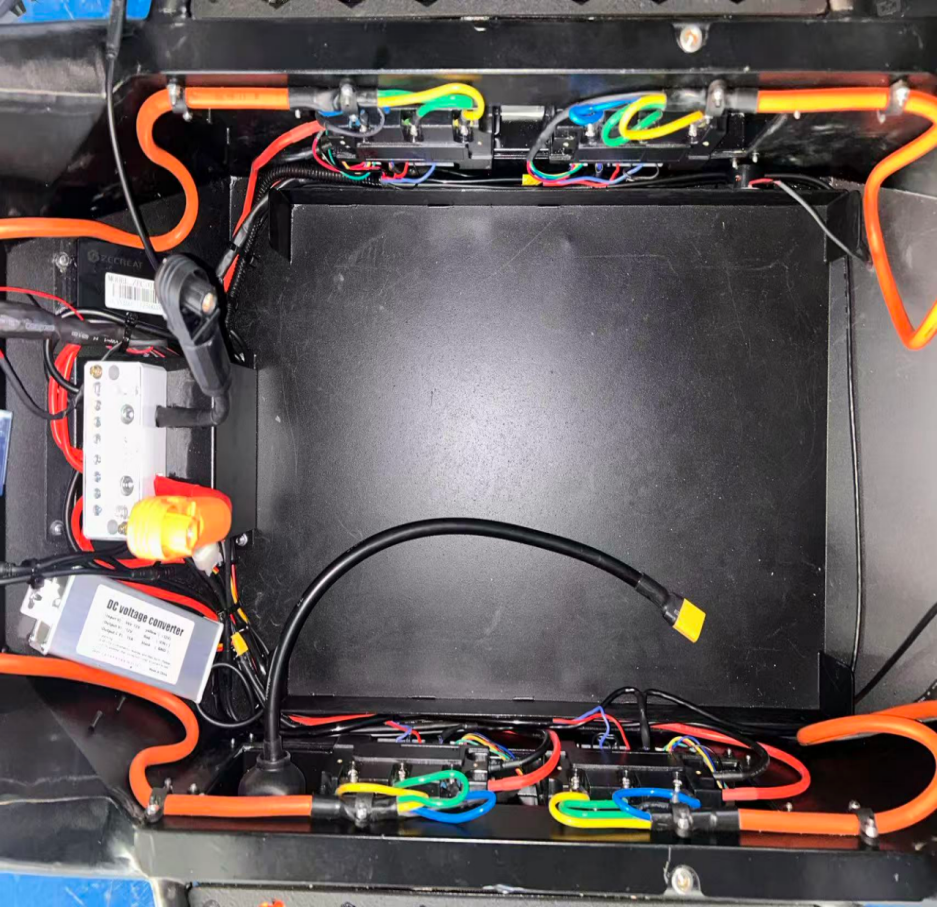
Wiring junction box assembly
When the junction box is facing you, the ports from left to right correspond respectively to the rear left, front left, front right, and rear right controllers.
Step 17
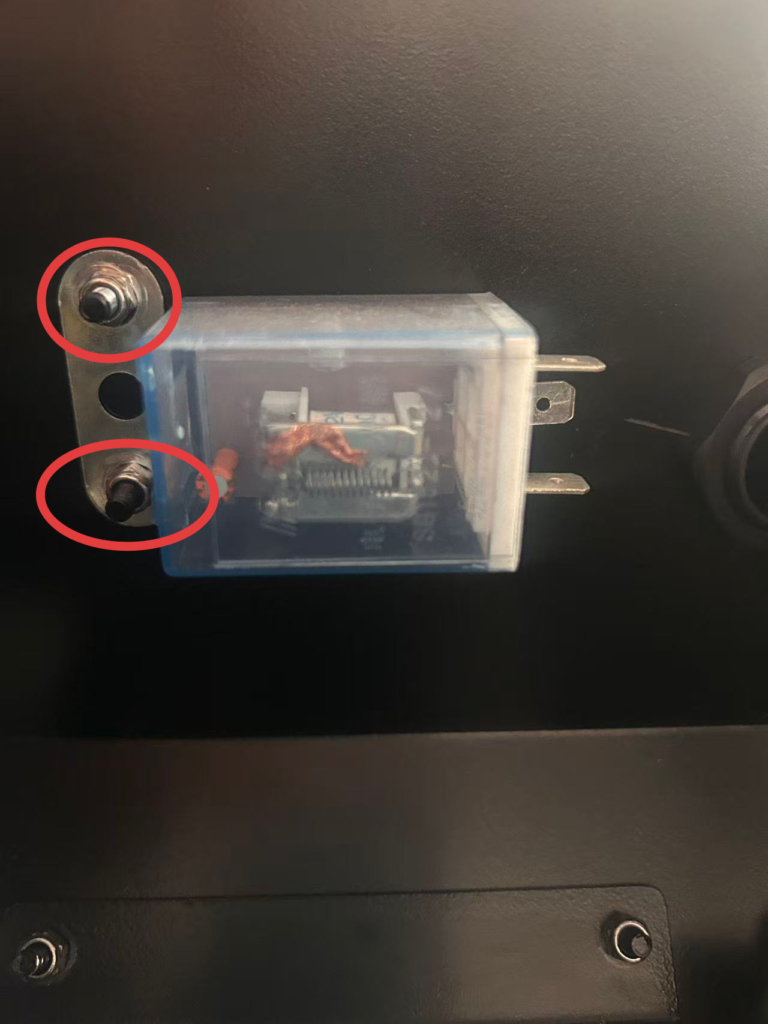
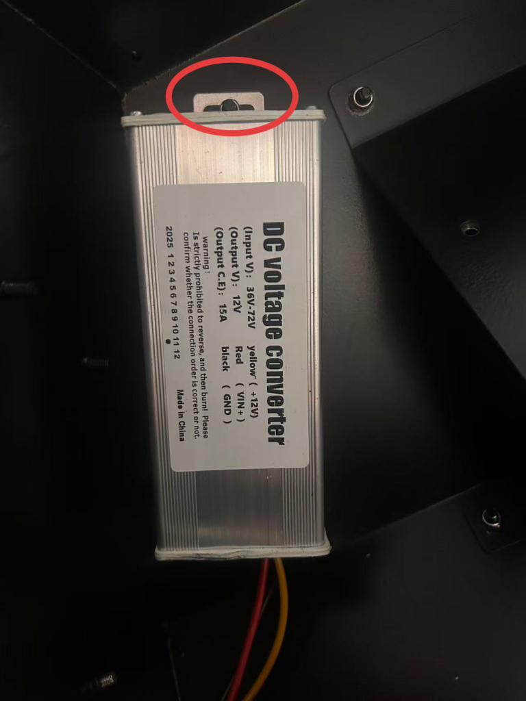
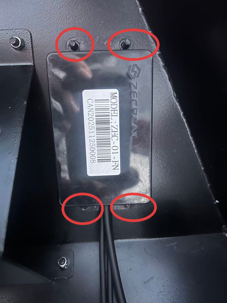
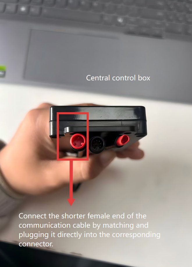
Flasher, DC converter, and central control box installation
Step 18
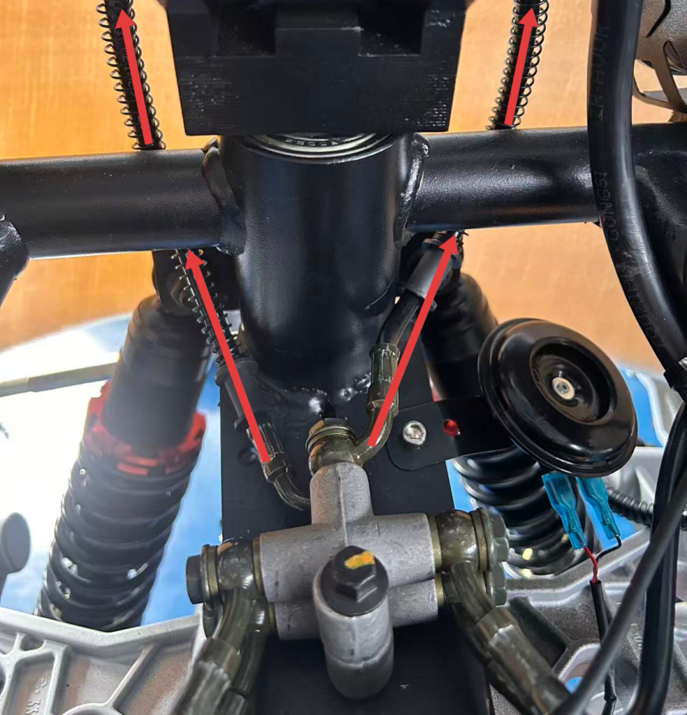
Controller wiring harness installation
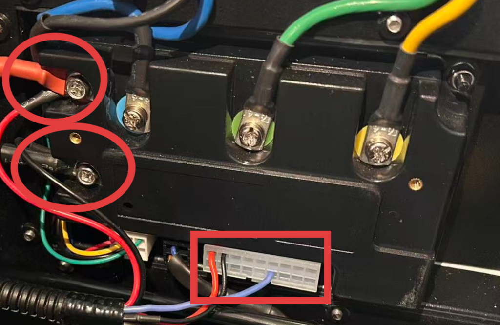
Make sure all connections are in the correct positions.
Step 19
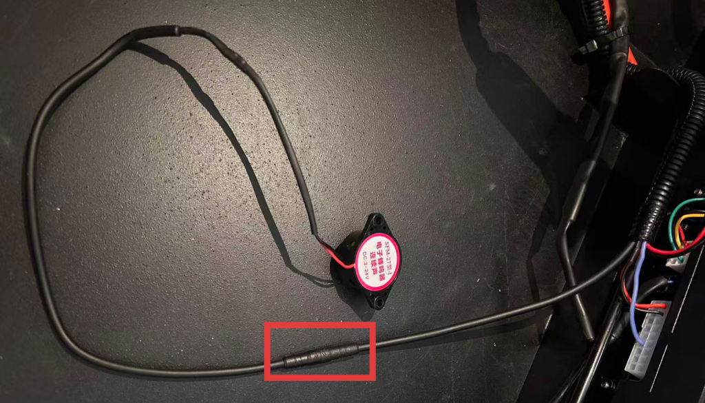
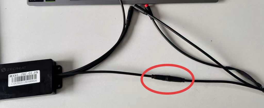
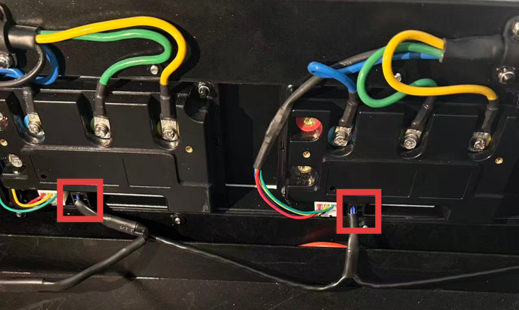
Communication wiring harness installation
Step 20
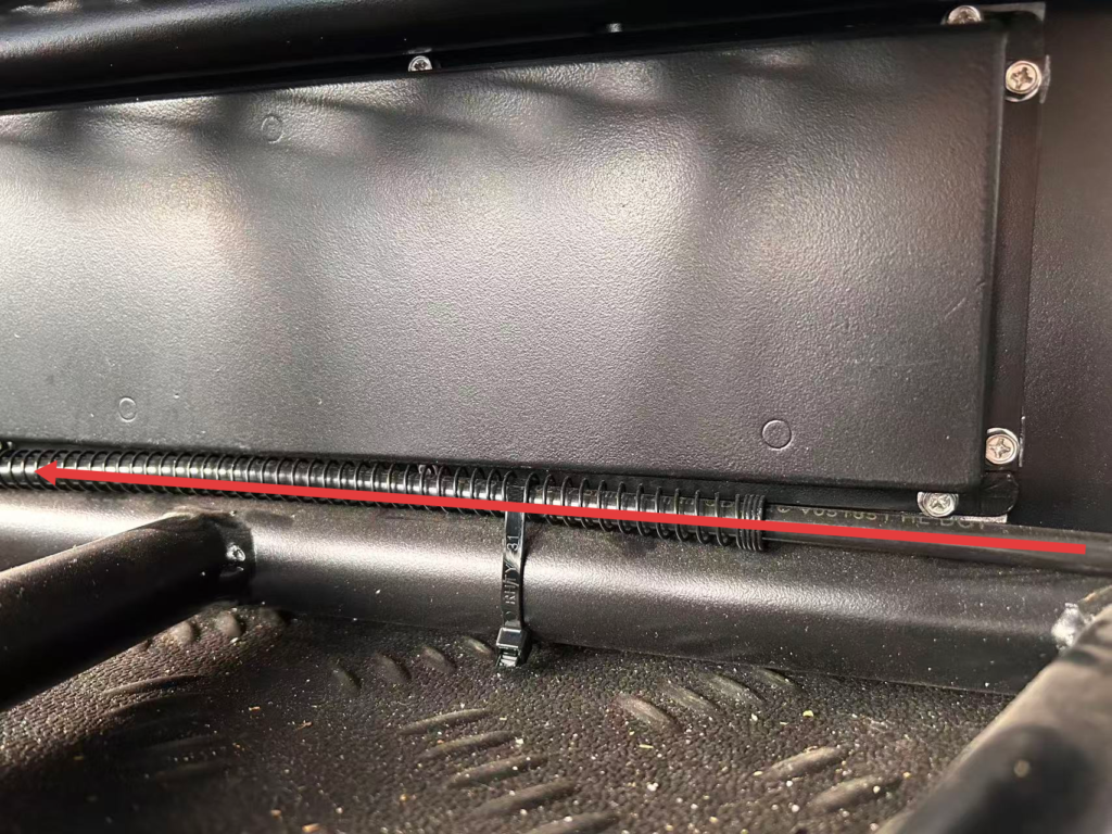
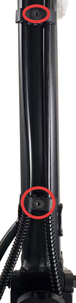
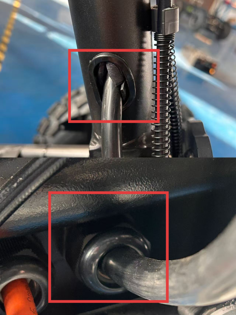
Main wiring installation
Step 21
Main wiring installation
The remaining length of the cable ties must not exceed 2 mm.
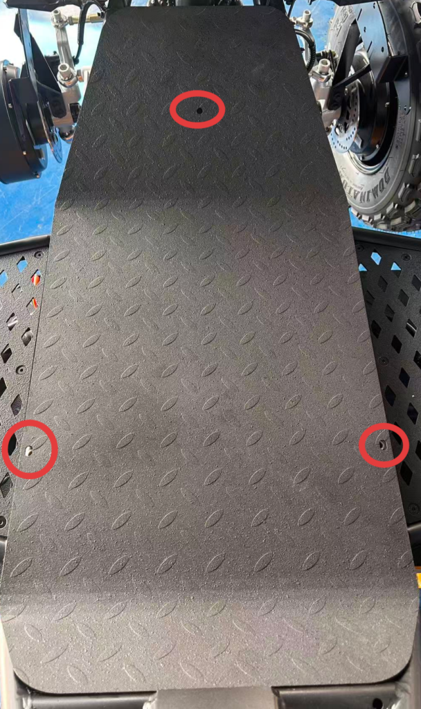
Step 22 Footboard Installation
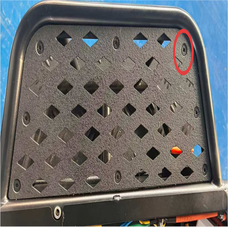
Install the side footboards. When tightening the screws, tighten them diagonally in a crisscross pattern to ensure even force distribution, and make sure the screw heads are flush with the footboard surface.
Jinhua FINO Technology Co., Ltd specializes in 4WD stand-up off-road vehicles designed for extreme terrain, rescue, and outdoor exploration. Built for performance, control, and all-terrain adaptability, redefining hardcore off-road experience.
Visit Us
Address: Room 301, Unit B, Building 5, No. 588 Dengyun Street, Tangxi Town, Wucheng District, Jinhua City, Zhejiang Province